project skills

Aerodynamics

Text Box: 1.	Introduction
Please write down the 100-150 words (the ones you did in week 3) about the general topic and insert the reference list for this post only:

Introduction

Aircraft design is fundamentally a subset of engineering design. Firstly, designing is an analytical procedure, and usually is joint drawing or drafting. Design has its own structure of knowledge, separated from the science-based analytical tools often cooperate with it. Design is a more sophisticated version of problem-solving technique that a lot of people use it regularly. Design is thrilling, demanding, satisfying, and rewarding (Sadraey, 2024).

The standard process for solving a mathematical problem is straightforward. Design is far more subjective, with several possible answers rather than a single correct answer. The world of design contains lots of difficulties, unpredict abilities, vagueness, and inconsistencies (Sadraey, 2024).

  Basically, there are three essential operations are involved in the design procedure, which are: analysis, synthesis, and evaluation. A fundamental and uncomplicated model of a design procedure is displayed schematically in Figure 1 (Sadraey, 2024).

Text Box: Figure 1. simplified model of layout process. Taken from (Sadraey, 2024).
A diagram of a process

Description automatically generated

Analysis is the performance or behaviour prediction process of a potential design (Sadraey, 2024).  Evaluation includes calculating performance and comparing the predicted performance of each possible design candidate to identify and flaws. The noun synthesis describes a process of combining two or more elements to create something new (Sadraey, 2024).

Design of aircraft is impacted by number of problems not the least is the economic considerations for the desired aircraft whether it is for civilian or military purposes. But nowadays the recent strategy of aircraft design is somehow connected to the industrial growth, which can be able to make rely on national infrastructure, governmental regulation and rules, workforce capabilities and raw materials. These are basically connected to the international economic and political conditions (Kundu, et,. al, 2019).

Introduction reference list

Kundu, A.K., Price, M.A. and Riordan, D., 2019. Conceptual aircraft design: an industrial approach. John Wiley & Sons.

Sadraey, M.H., 2024. Aircraft design: A systems engineering approach. John Wiley & Sons.

Text Box: 2.	Main Post one
Write about your general topic. For instance, introduction, theory, advantage, disadvantages, and the reference list for this post only…...etc.

Main post 1

Many aircrafts are design as fixed-wing vehicles and are widely recognised as airplanes.  A fixed-wing aircraft is a type of aircrafts that is heavier than air, that has the capability of flying in the air through producing lift by its wings. An aircraft with an operated engine is basically called an airplane Figure 2. (Sun, Adnan, 2021).

an aircraft has several incorporated components, as displayed in Figure 3. Typically, these components can be classified into straightforward mechanical parts for example wing, fuselage, landing gear, tail units (horizontal and vertical stabiliser), also control surfaces like aileron, rudder, and elevator. (Sun, Adnan, 2021).

Text Box: Figure 2. the general shape of the fixed-wing aircraft (airplane) taken from (Sun,  Adnan, 2021).
A grey airplane with white background

Description automatically generated with medium confidence

The major structural component in the airplane is the fuselage. It gives room for load, control system and pilots, travellers and cabin crews, and other additions and equipments. The fuselage houses the power plant in the single engine aircraft. A fuselage has access to diverse structures that it can be built by like truss, semimonocoque, and monocoque (Sun, Adnan, 2021).

Also, carrying the air is the main purpose of the wing and power plant loads and transfer them to the fuselage. the wing’s cross-section shape is the same shape of an airfoil, which is structured based on aerodynamic matters. Basically, wings are designed based on monospar, multispar, or box beam (Sun, Adnan, 2021).

Text Box: Figure 3. general components of the airplane. Taken from (Sun, Adnan, 2021).
A diagram of a plane

Description automatically generated

Text Box: The resulting stress equation, taken from (Sun, Adnan, 2021).

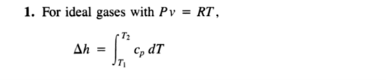
axial members are designed to carry extensional or compressive loads applied along their axial direction, resulting in uniaxial stress:

 While E and  stand for the Young’s modulus and normal stress, in row, in the loading direction. The utter axial force  given by the member is

Text Box: The equation of the axial member force F. taken from (Sun, Adnan, 2021).

In the provided scenario, A stands for the member’s cross-sectional area, δ denotes the axial displacement and L symbolizes the length of the axial member. EA is a term that sorts out the axial rigidity which, on the one hand, depends on the elasticity and, on the other hand, depends on the member’s cross-section area. It is all clear that the transformation of the cross-section’s shape has no effect at all on the axial stiffness. By way of illustration, the circle and the channel section can both confidently take the same load provided their cross-sectional areas are the same (see Figure 4).  The bending load is known that is directly relative to the buckling stiffness and inversely relative to the square of the effective length (Sun, Adnan, 2021).

A black and white line art

Description automatically generated
Text Box: Figure 4. The round bar on the left, and the channel on the right. Taken from (Sun, Adnan, 2021).

  Through shortening the buckle mode, the buckling strength can be increased by increasing the bending stiffness. The channel section is better in buckling resistance due to its larger bending stiffness as compared to a circular section. Nonetheless, the bending stiffness of most axial members used in aircraft such as stringers is usually a very small amount because of their slenderness, and as a result, it is inadequate to achieve the required buckling strength. To address this issue, the buckling strength of axial members is typically increased by using lateral supports along their length and rigid ribs in the wings and frames in the fuselage (Sun, Adnan, 2021).

The structure of aircraft has improved over time form the classical structure style to more up to date computer-based design method utilising multivariate structural optimisation. The diversity and complexity of aircraft’s concept which has developed, lots of synthesis packages were pushed beyond their capabilities. Each concept needs an independent package because it was focused on the analysis of one particular concept by several examples of the aircraft structure (Smith, et., al. 2019).

The incorporated design “flying wing” (FW), or “blended wing body” (BWB) is recognised to be the ideal aerodynamic design for long-range aircraft. Full removal of the fuselage as a major component of drag, was the aim of the flying wing idea. Additionally, the empennage is also absent in a classical flying wing design. Theoretically, the lift to drag percent of flying wing can be up to 40% higher than that classical design for the same wing aspect percent. Moreover, due to the probability of more uniform distribution of cargo inside the wing, the design of the flying wing for the aircraft empty weight which have to be less. Therefore, more complicated issues of balancing and controllability of flying wing without doubt lead to losses (chernyshev, et,. al. 2019).

 Substantial structural height of the wing is required to enhance the comfortability of travellers, which a factor can lead to a considerable increase of absolute aircraft sizing is standard small comparative thickness. The only reasonable applications of these enormous flying wing aircrafts for top high transportation capacity (1000 traveller). According to challenges of incorporation of that kind of aircrafts into existing transportation flows and safety purposes that kind of aircrafts have not tested seriously yet (chernyshev, et,. al. 2019).

At the dawn of CFD, its implementation in the industry was seen in a lukewarm light by aerodynamicists who have been in practice for a long time, they were partly afraid that it might reduce their workloads. But, it was soon found that CFD was just a new approach that could add to the understanding and analysis of designs. The introduction of this new technology was particularly the key factor for aerodynamicists, as they had to gain the knowledge to operate the tool and find a new way of working with the tool in the process of analysis and design (Martins, 2022).

Other than understanding the design, CFD analysis, which usually leaves out, if not the last, then an important part of the engineering work, also has to the need for promoting it. The method of combining the resource of CFD analysis with numerical optimization is recently the more effective way to advance the designs according to Mr. Minutes to successful. But, the optimization of the aerodynamic design using CFD may lead to the same difficulties as when CFD was first introduced into the industry years ago. Even though this new tool apart from the many challenges it faces and can be considered a tool that has the potential to improve the aerodynamic design process, it also comes with problems of its own (Martins, 2022).

 They could even be considered as a basis because CFD, which is the parent to the children in the newer generation of aerodynamicists, is the preliminary stage to design [the children of aerodynamicists]. Nevertheless, the deeper the understanding of design optimization is, the more and more urgent it becomes for conventional aerodynamicists to cultivate this art. Otherwise, they will be limited in their activities and will be restricted in the sector variety (Martins, 2022).

In the ADflow open-source CFD solver, the ANK approach was done, ADflow has the capability of evolving the steady-state solution to the RANS equations even for naturally irregular flow fields.  According to the backward Euler algorithm, steadies physically unstable forms. An instance is presented in Figure 5 of a flow solution. While the Common Research Model (CRM) of NASA is done at a 90 degrees angle of attack at M= 0.85. Also, the resolution in this instance is not physically real, the key point is that the flow solver productively evolves. Also, by Burgess and Glasby this instance was inspired by the 90-degree angle-of-attack airfoil resolution (Martins, 2022).

A close-up of a plane

Description automatically generated
Text Box: Fig. 5.Anil Yildirim's demonstration of the robustness of the ADflow solver leads to the achievement of a converged RANS solution for the CRM configuration at a 90-degree angle of attack and Mach 0.85. Taken from (Martins, 2022). 
(Martins, J.R., 2022).

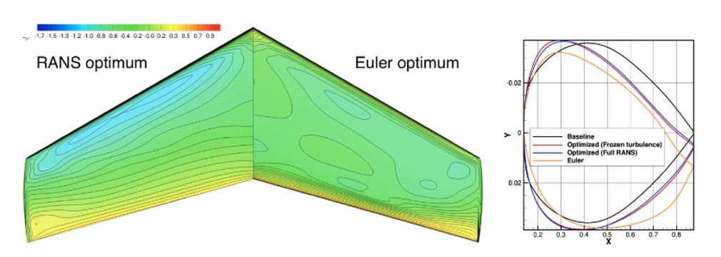
An instance by using MACH-Aero demonstrates an optimisation process, that begins from a circular and evolves into a supercritical airfoil throughout fully automated optimisation, as shown in Figure 6. Once more, the circular intermediate shapes of the flow solution are not realistic, nonetheless, the derivatives with respect to shape have the right trend for drag reduction. As the shape nears the optimum, the RANS solution becomes accurate. Intermediate inaccuracies are irrelevant as long as the optimizer ultimately converges to a case where the solution is valid (Martins, 2022).

Text Box: Fig. 6. Minimization of drag with forcing function moment on lift and moment, and initially being circular-shaped configuration Mach= 0.734, Cm= 0.824, Cm-0.092. Taken from (Martins, 2022).
A colorful logo with a white circle

Description automatically generated

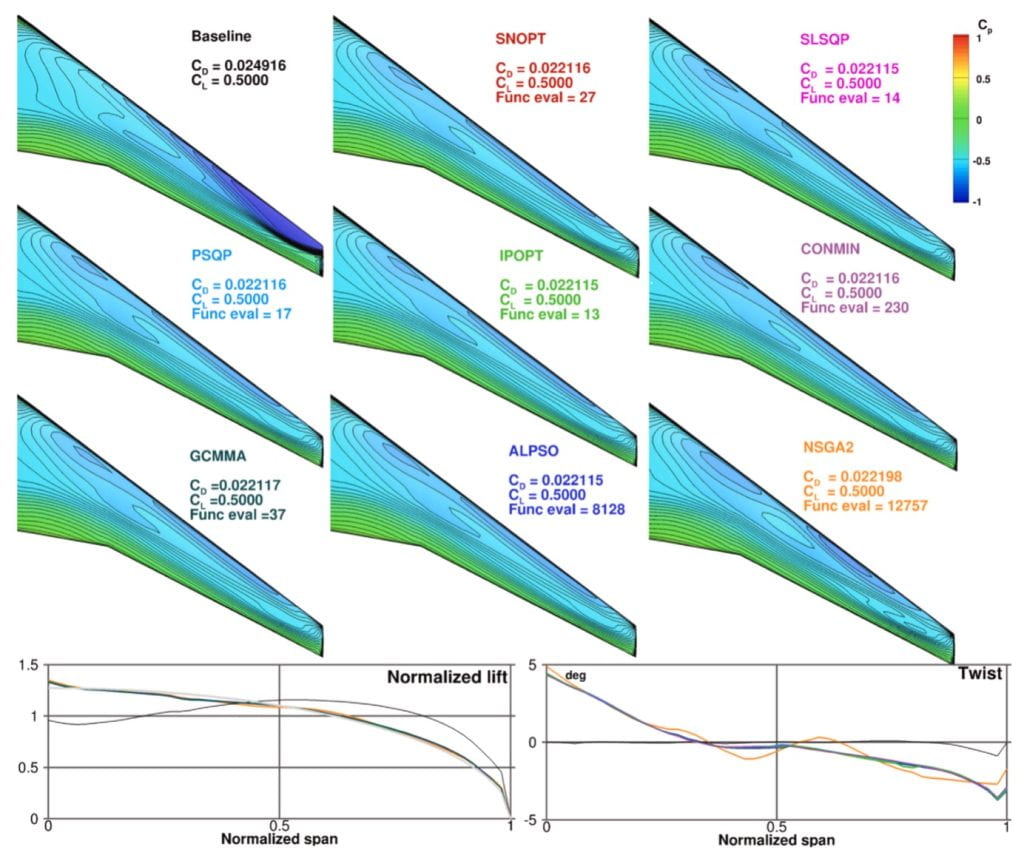
Two efficient optimization methods, as well as two gradient-free optimization algorithms, have been put to the test in Figure 7 of scalability, their names include NSGA2 and ALPSO for the latter, and SLSQP and SNOPT for the former, thereby, were utilized to solve a multidimensional Rosenbrock problem. All four scenarios of those methods were criticized to evaluate them in the context of a more practical situation, that just used all kinds of optimizers on a CFD-based wing twist problem. This, which involved only nine parameters, was a morphing problem based on the limit of the twist variable and used a rather coarse mesh, was aimed at making the optimization in the absence of gradients using the NM algorithms possible. The needed optimised λ o, as noted above, was to make a balance between the drag coefficient minima and a lift coefficient constraint though Still squared gradients when the algorithm was checked. Gradient-based algorithms were common end-users of around 14 to 230 function evaluations, which were very different from gradient-free algorithms that needed several an emanation like the one over 8000, for an airfoil optimisation problem (Martins, 2022).

Text Box: Fig. 7. To get rid of the exaggerated number of design variables needed to improve aerodynamic shape, you need to use the Gradient-based optimization, it is the only viable approach. Taken from (Martins, 2022).
A graph showing the difference between two different design variables

Description automatically generated

The used process for the work above is SNOPT, a gradient-based algorithm that apply sequential quadratic programming and have the ability to deal with nonlinear restrictions. To assist the framework, the SNOPT was enclosed, (a Fortran library) with Python throughout the pyOptSparse wrapper. Furthermore, assisting the incorporation with the other modules of the framework, pyOptSparse gives a usual interface to several optimisation algorithm; to try a different algorithm, in the main run script, a flag only needs to be changed. Using this facility, to be able to do all the results shown in Fig. 8. (Martins, 2022).

Text Box: Fig. 8. When considering optimizers for a wing design problem, we recognize in ourselves that there are 9 more twist variables it adds up to the fact that gradient-free methods require computational effort around 2-3 orders of magnitude more than simple problems for optimization. Taken from (Martins, 2022).
A collage of different types of curves

Description automatically generated with medium confidence

The two essential classifications of numerical enhancements: gradient-free and gradient-based techniques. For great values measurements, great fidelity enhancement of aerodynamic issues relies on computational fluid dynamics (CFD), the mixture of a gradient-based optimiser and the adjoint way for computing the demanded gradients has shown to be the greatest efficient way. In fact, the Inevitable feasible decision when the value of layout varying go beyond 100 or so (He, et,. al. 2019). 

Main post 1 reference list

Chernyshev, S.L., Lyapunov, S.V. and Wolkov, A.V., 2019. Modern problems of aircraft aerodynamics. Advances in Aerodynamics, 1(1), p.7.

He, X., Li, J., Mader, C.A., Yildirim, A. and Martins, J.R., 2019. Robust aerodynamic shape optimization—from a circle to an airfoil. Aerospace Science and Technology, 87, pp.48-61

Martins, J.R., 2022. Aerodynamic design optimization: Challenges and perspectives. Computers & Fluids, 239, p.105391.

 Smith, H., Sziroczák, D., Abbe, G.E. and Okonkwo, P., 2019. The GENUS aircraft conceptual design environment. Proceedings of the Institution of Mechanical Engineers, Part G: Journal of Aerospace Engineering233(8), pp.2932-2947.

Sun, C.T. and Adnan, A., 2021. Mechanics of aircraft structures. John Wiley & Sons.

Text Box: 3.	Main Post two
Write more about your specific question. you should show a case study, pictures, data, charts, and the reference list for this post only…...etc.

Main Post 2

Case Study: Effects of wing flexibility on aerodynamic performance of an aircraft model.

At the beginning, the basic aircraft model was chosen to apply the low-speed wind tunnel experiment to discover the affection of wing flexibility on the aircraft aerodynamic performance. Measurements of force, like Layer Distortion, velocity field, and constant of Reynold which equal of 5.4 1045 , are included in the experiment. In the lift curves, couple of heights are detected (Qinfeng, et,. al. 2021).

the stall is corresponded to the initial height, and the wing sensitivity is more flexible than the first height, which approximately stay consistent. For the optimal case, compared to the rigid wing model, approximate of 5o are achieved of delayed stall. And the raise of the relative lift is about 90% (Qinfeng, et,. al. 2021).

It shows that the lift improvement region corresponds to the bigger distortion and stronger shaking, which leads to more intensive flow mixing close to the flexible wing surface. Therefore, the leading-edge separation is dominated, the performance of aerodynamic is enhanced substantially (Qinfeng, et,. al. 2021).

In the aircraft layout world, the persistent chase of designers is for better aerodynamic characteristics. Additionally, using flaps to adjust the wing’s camber and surface area to generate extra lift during low-speed flights, but by causing asymmetrical rotation of the wing, the aileron creates moments. Recently, morphing which stands for the vehicles’ capability to accomplish smooth external form adjustment, has attracted more attention (Qinfeng, et,. al. 2021).

However, the aerodynamic opinion says that the benefits of morphing wing have long been acknowledged, the layout complexity, as well as a sequences of technical issues, controls its practical application (Qinfeng, et,. al. 2021).

The length of the whole body is 219.3 mm and the diameter is 40 mm. It has an ellipsoidal cone-like shape, with the wing root’s leading edge located 101.3 mm from the nose. The Figure 9(a) on the page shows the outline drawing of the model which denotes the wing leading-edge sweep angle (Λ) as 15°. The leading edge’s inner part remains straight, while the outer section curves elliptically, as seen in the Figure 9(b) (Qinfeng, et,. al. 2021).

Text Box: Figure 9(a) (Qinfeng, et,. al. 2021).  diagram of experimental model
A diagram of a plane

Description automatically generated
Text Box: Figure 9(b) diagram of experimental model (Qinfeng, et,. al. 2021).
A close-up of a model of a jet

Description automatically generated

For force measurements, a model was fitted onto the tail of a six-component strain balance as described in Fig. 10. Installed into the tail end of the panel was the balance with the help of a tapered fit. Each force data was collected from about 2000 sample points that were time-averaged over 20 seconds. A servo mechanism with a range of 0° to 60° was used to change angle of attack and an accuracy of 0.05° was maintained. The angle of attack (α) was varied at α = 60° and drag blockage was below 5% so it was not necessary to perform drag corrections. The angle of attack was adjusted by 1° down to 0° and promoted by 2° from 1° to 50°. These were the Reynolds numbers = 5.4×10⁴ to 10.8×10⁴ corresponding to the wing root length. The repeated measurements showed an uncertainty of less than 3% (Qinfeng, et,. al. 2021).

Text Box: Figure. 10. illustration of the PIV experiment setup and distortion measurement procedure, taken from (Qinfeng, et,. al. 2021).
A diagram of a laser measurement

Description automatically generated

To discover the secret behind the better aerodynamic performance of the flexible wing, the velocity fields of both rigid and flexible wings with Λ = 15° were analysed using Particle Image Velocimetry (PIV). The MicroPIV system was composed of an array of devices, including a Charge Coupled Device (CCD) camera, the light source of a Nd:YAG double-pulsed laser, and the ethylene glycol droplets as the tracer particles. The power and the wavelength of the laser were 500 mJ and 532 nm respectively. The camera, whose resolution was 2456 × 2058 pixels, captured a field of view that was about 100 mm × 80 mm, and hence the magnification was 0.04 mm/pixel. The laser and the camera were operated with a time interval of 20 μs and a sampling frequency of 4 Hz. In a single experiment, 5000 instantaneous velocity fields were recorded (Qinfeng, et,. al. 2021).

A Fastcam Photon SA2 CMOS camera working in conjunction with a laser source continuously captured the change in the shape of the membrane. The camera and the laser setup configuration were exactly the same as for the PIV measurements, while Fig. 10 gives the true picture. The camera had 2048 × 2048 resolution and provided a field of view of 90 mm × 90 mm, which gave a magnification of 0.04 mm/pixel. The laser operated at a power of 8 W and had a wavelength of 532 nm. The shape of the object after the deformation was recognized by the boundary recognition algorithm, and pixel coordinates were transformed into physical coordinates by the calibration process. Thenceforth, the deformation of the flexible upper surface of the wing was observed with the measured section being consistent with the experimental Reynolds number and the results from the velocity measurements, i.e., Re = 5.4 × 10⁴ (Qinfeng, et,. al. 2021).

The figures 11 and 12 are used as time-averaged streamlines, and the red lines are used to show the deformation of the flexible wing’s upper face that is averaged over time. The flexible wing is one in that the flat initial section on the upper surface is caused by the attachment between the rigid leading edge and the flexible membrane. For the rigid wing, its configuration remains unchanged throughout the experiment. The flexible wing results are shown for angles of attack (α) of 6°, 10°, 20°, and 40° i.e., the pre-stall regime, the vicinity of stall, the growth phase of deep stall, and the region near the decline phase of deep stall. Meanwhile, the results for the rigid wing at the same angles of attack are also included to facilitate comparison (Qinfeng, et,. al. 2021).

Text Box: Figure 11 (a) results of rigid wing at , α=6o . taken from (Qinfeng, et,. al. 2021).
A diagram of a graph showing a curve

Description automatically generated with medium confidence
Text Box: Figure 11 (b) the results of the flexible wing at,α=6o . taken from (Qinfeng, et,. al. 2021).
A graph showing a curve

Description automatically generated with medium confidence
Text Box: Figure 11 (c)the results of the rigid wing at, α=10o . taken from (Qinfeng, et,. al. 2021).
A diagram of a waveform

Description automatically generated with medium confidence
Text Box: Figure 11 (d)the results of the flexible wing at, α=10o . taken from (Qinfeng, et,. al. 2021).
A diagram of a person's eye

Description automatically generated
Text Box: Figure 12 (a) the results of the rigid wing at, α=20o . taken from (Qinfeng, et,. al. 2021).
A blue and white diagram with lines

Description automatically generated with medium confidence
Text Box: Figure 12 (b) the results of the flexible wing at, α=20o . taken from (Qinfeng, et,. al. 2021).
A diagram of a wind

Description automatically generated
Text Box: Figure 12 (c) the results of the rigid wing at, α=40o . taken from (Qinfeng, et,. al. 2021).
A diagram of a house

Description automatically generated
Text Box: Figure 12 (d) the results of the flexible wing at, α=40o  taken from (Qinfeng, et,. al. 2021).
A blue and white grid with a red line

Description automatically generated

Reference list of the case study (main post 2).

Qinfeng, G.U.O., Xi, H.E., Zhuo, W.A.N.G. and Jinjun, W.A.N.G., 2021. Effects of wing flexibility on aerodynamic performance of an aircraft model. Chinese Journal of Aeronautics, 34(9), pp.133-142.

No Comments »

introduction

Heat transfer is energy transferred by virtue of a temperature difference. It flows from regions of higher temperature to regions of lower temperature; the basic modes can write into three methods as follows:

  1. conduction
  2. radiation
  3. convection (Rohsenow W M, Hartnett J P, Cho Y I.1998.)

Conduction is a process where the energy transfer from a region at a high temperature to a low temperature region is governed by the molecular motion as in solid bodies and fluids at rest and by movement of electrons as for metal. (Carey V P, Chen G, Grigoropoulos C, et al., 2008,)

Radiation is electromagnetic radiation emitted by a body by virtue of its temperature and at the expense of its internal energy. ( Rohsenow, Warren M., James P. Hartnett, and Young I. Cho. 1998.)

Convection is a separate mode of heat transfer, relates to the transfer of heat from a bounding surface to a fluid in motion, or to the heat transfer across a flow plane within the interior of the flowing fluid. (Rohsenow, Warren M., James P. Hartnett, and Young I. Cho. 1998.)

Reference list

Rohsenow, Warren M., James P. Hartnett, and Young I. Cho. Handbook of heat transfer. Vol. 3. New York: Mcgraw-hill, 1998.

Carey V P, Chen G, Grigoropoulos C, et al. A review of heat transfer physics[J]. Nanoscale and Microscale Thermophysical Engineering, 2008, 12(1): 1-60.

No Comments »

main post 1

What is heat transfer in nuclear factory
 
Just like definition Heat is defined as energy transferred by virtue of a temperature difference, The heat transfer in nuclear factory is also follow this definition. Despite all the cosmic energy that the word “nuclear” invokes, power plants that depend on atomic energy don’t operate that differently from a typical coal-burning power plant. Both heat water into pressurized steam, which drives a turbine generator. The key difference between the two plants is the method of heating the water. (Brain.M et 2000, 9.) so the nuclear factory just uses different ways to create heat then heat up water to form steam, to make steam engine move.
Different from traditional fossil fuel factory, the nuclear factory produces heat by nuclear fission, when one atom splits into two and releases energy. (Brain.M et, 2000, 9.) Just like the uranium constantly undergoes spontaneous fission at a very slow rate, so it can be used for the induced fission.
 
How nuclear power plants work and structure of nuclear power plants
 
Although the nuclear factory work theory is same as traditional fossil fuel power station, the efficiency of nuclear factory compares with other power station have a giant difference.
How the heat transfer is used in nuclear factory.

Diagram 1.1
(based on this diagram it shows the concrete structure inside the nuclear power plant)
 
Inside a nuclear power plant
 
According to principle of nuclear factory, this factory is using the one atom splits into two and releases energy, so in a fixed amount of uranium plenty of uranium atoms collide each other, it causes a lot of heat to be generated.
Then those heat energy will transmit by increases into steam generator the temperature of the pump increase rapidly, the motivation of molecules in the pump increase rapidly because of the hyperthyroid, those moving with high-speed molecules will transfer heat energy to the water molecules, to let the temperature balanced which cause the temperature of water in steam generator will have rapidly temperature increase. The speed of water molecules movement increases the gap between each molecules is little by little widen, when the distance between each molecular reach certain data, the steam will form and then the steam will extraction by the steam line in a constant velocity, it cause the steam have an initial velocity to let the turbine move, at same time the turbine will let the generator move to produce electric energy.
In cooling water condenser area the pump will continuity transport cooling water , the steam contact the cooling water ,it need to maintain the heat transfer between each molecules so the distance between each molecules decrease gradually ,and the water will formed again ,those water will extract by the pump back to the steam generator again, this is how a steam nuclear power plant works and how the nuclear factory use the heat transfer.
 
Outside a nuclear power plant
 
Once you get past the reactor itself, there’s very little difference between a nuclear power plant and a coal-fired or oil-fired power plant, except for the source of the heat used to create steam. But as that source can emit harmful levels of radiation, extra precautions are required. (Lamb, R. (2000).
 A concrete liner typically houses the reactor’s pressure vessel and acts as a radiation shield. That liner, in turn, is housed within a much larger steel containment vessel. This vessel contains the reactor core, as well as the equipment plant workers use to refuel and maintain the reactor. The steel containment vessel serves as a barrier to prevent leakage of any radioactive gases or fluids from the plant. (Brain, Marshall, and Robert Lamb. 2000)
 
The advantages and disadvantages of nuclear factories and the heat transfer usage in nuclear factories.
 
In nuclear factory, the efficiency of this factory is always higher than another factory


  Diagram 1.2
From the nuclear factory theory, this factory only need less uranium to start the reaction and this reaction will go on for ages compare with other traditional power station, those need Continuous fuel input, so the nuclear factory is more save sources than other factory and then the water used in nuclear factory can be reused in factory but in traditional power station ,those fuel burned will produce plenty of harmful gases such as carbon dioxide, sulfur dioxide, when those gases produced it will accompany high temperature which cause the nitrogen will react with oxygen to form nitrogen dioxide ,one of the toxic gases.
In cost the nuclear factory is also more favorable than other factories in picture, the unit energy production cost of nuclear factory is lowest compare with other two non-renewable sources factory only 3.00 to 8.20 cent per KWh, other factory like coal power station is 4.50 to 8.50 so nuclear factory is more inexpensive.
Then in nuclear factory the thermal loses is less than other factory, in nuclear factory, there are not need to burning fossil fuels to produce heat energy which means
It will not react with oxygen to produce carbon dioxide, in traditional power station the carbon burned in air, the carbon dioxide will produce, and the carbon dioxide will bring some heat emission to surroundings, it will cause thermal loses.
Although there are a lot of advantage of nuclear factory .there are also some negative impact of this factory , in this factory , plenty of water needed to cooling the pump , the pump is very close to the nuclear reactor ,so the water will get radiation which cause the water in nuclear factory cannot direct to nature , the factory must to purified nuclear wastewater ,plenty of money will cost in it.
On the other hand, the nuclear reactor in nuclear factory is very unstable, if operator neglects inspection or the temperature in reactor too high, it will happen explode hundreds of miles around will be influenced by this explode, after exploding, those hundreds of miles will be full of radiation, if this case happen the consequences are unimaginable.


Reference list


Brain M, Lamb R. How nuclear power works[J]. HowStuffWorks. com, 2000, 9.


Koval A, Chala K. Advantages and disadvantages of nuclear power[J]. 2018.


Nellis G, Klein S. Heat transfer[M]. Cambridge University Press, 2008.


Adar E. The State of the Art of Nuclear Energy: Pros and Cons[C]//EurAsia Waste Management Symposium. Istanbul. 2020: 26-28.

No Comments »

main post 2

The principle of heat transfer

If we want to more deeper understanding the heat transfer, we need analysis the heat transfer process by using some thermodynamic concepts, like the first law of thermodynamics which talk about the principle of conservation of energy. but if we want to use this law, we need to attention some condition for this law can show it right, we need to make sure the surrounding is open or closed, and is that the reaction is stable, after we consider those condition, we can use this formula

Figure 1.1

(THE Delta U  is change in internal energy within system)

(the Q Delta t is heat transferred into the system)

(the Q v Delta t is heat generated within the system)

So, if we are dividing the Delta t the formula will become:

The Delta t are almost zero data so there is no heat transfer happen at these surroundings

However, in nuclear factory it will not happen energy conservation, so we need to consider other conditions heat transfer.

In nuclear factory, if there are no external work is done and changes in kinetic energy and potential energy are negligible

The formulae of this mechanism can be written at :

The value of Delta h is variable at different condition

(where P means pressure, V means volume)

Another condition is:

Those two formulas is the basic heat transfer calculate formula.

The material influences the heat transfer

After talking about the environment factor, the material of nuclear factory also will influence the usage of heat transfer

                                               Figure 1.2

This figure shows the thermal conductivity of different material at 300k

Obvious different material at same temperature, the thermal conductivity is different when the nuclear factory is established, the material must consider, the temperature in nuclear factory is almost 200 degrees centigrade even higher than it, so carbon steel, stainless steel and special alloys, which have lower thermal conductivity and can defend 200 even higher temperature.

In nuclear factory, there are not only the nuclear reactor full of radiation, the higher temperature emits by the reactor also have radiation

                                                   Figure 1.3

This figure shows the different material emittance of radiation, carbon steel, stainless steel and special alloys, have lower emittance than most material, that is why inner shell of nuclear reactor use those material.

But from main post 1 picture shows, there have a pump link between steam generator and reactor, it needs conduct temperature to make sure the temperature can let water become steam so the pump material must have good conductivity for thermal, polyethylene is used to make pump which have good thermal conductivity.

The different mode of heat transfer

In nuclear factory, there is not one mode of heat transfer in it, when the reactor emits heat energy, the heat will be conducted by the air, or the heat energy will emit radiation to transmit energy in it.

                                                                Figure 1.4

Just like the figure shows :the first part is two different thickness walls ,when the temperature 1 contact the layer A the temperature 1 is conduct by the layer A, and some heat is absorb by the layer A to form temperature 2 the temperature because of the thickness of this wall is more thicker than layer A so more energy absorbed by layer B ,it is obviously see how the temperature decrease in layer B to form temperature 3 ,why the temperature is different after is transmit different thickness wall ,that is because this formula:

Different length and the area are all will influence the result.

On the other hand, the radiation also will influence the temperature, like figure show:

                                                                 Figure 1.5

In nuclear factory, when the heat across the wall or other material layer the heat will lose some energy, at the same time, the heat will happen thermal convection, the temperature will decrease by collide hot flux, then there are also have radiation in surroundings, the radiation has thermal resistance the temperature will decrease again.

With formula:

(the 1 divide by hrA means a radioactive thermal resistance)

The influence of heat transfer by different state

 When heat transfer is underway, except for the material we need to consider, the have other factor will influence the efficiency of heat transfer, it called transient thermal response.

It depends on the different state: the steady-state (steady-state) and unsteady or transient.

Steady-state problem refers to the situation where the temperature does not change with time.

non-steady state or transient problems occur when the temperature changes with time.

In nuclear factory, the cooling tower area the water will use to decrease the temperature of the pump, the temperature change is just like this formula:

Considering all the factors of the heat transfer influence, it can combine with some factors, like convection and radiation.

                                                              Figure 1.6

Analyze those factors about the radiation factor, it has thermal resistance in it so it will transform some energy, by use this formula:

It can calculate the actual heat lost by the radiation, and then the convection it also have formula:

The original temperature minus those two factor it will calculate the final energy transfer (basic on there have not any heat resistance layer)

When we consider about time those all the formula will change their formal,for example the basic energy conservation formula will become:

or

In conclusion

those 4 points introduce the most usage of heat transfer in nuclear factory .”material, energy lost formula,different state will influence the heat transfer and how the radiation,convection influence heat transfer.”

Figure citation:

Figure 1.1-1.6 were cited from(Mills A F. Heat transfer[M]. CRC Press, 1992)

Reference list:

Mills, A. F. (1992). Heat transfer. CRC Press.

Heat transfer handbook[M]. John Wiley & Sons, 2003

No Comments »

Aerodynamics

Aerodynamics is the study of the properties of moving in the air and the interaction between the air and solid bodies moving through it. Aerodynamics has three main components (all with different advantages and disadvantages) and they are experimental, theoretical (can be analytical or semi-analytical) and computational fluid dynamics, the main focuses of these components are the forces of lift and drag (Rathakrishnan, 2013). The main use of aerodynamics is the design of vehicles like cars and airplanes as any engineer’s goal is to create an aerodynamic vehicle to minimize friction with air and maximize speed therefore fuel efficiency using what is called a ‘streamlined’ shape, another goal could be to create buildings that are more resistant to natural disasters using the same methods and maths used for vehicles however in the context of buildings (Roy, 2012).

References:

Rathakrishnan, E., 2013. Theoretical aerodynamics. John Wiley & Sons.

Roy, A., 2012. A First course on Aerodynamics. Bookboon.

As previously mentioned, aerodynamics has many main uses, one of the most famous of which being vehicles. All vehicles must utilise and or take into consideration aerodynamics in some way to function properly and efficiently. From a child’s bicycle to a NASA rocket, any mode of transportation had an engineer behind it who ensured it had the right design to optimise the efficiency of its movement through air and any other fluid for that matter, though that would not be called aerodynamics, rather another type of fluid dynamics. One of the key things you will notice in the world of aerodynamics is that it looks mainly at two forces, one of them being lift and the other drag (as well as their opposite forces of weight and thrust respectively) (see Figure 1). (DaSilva M, 2022)

Drag:

Drag is the force that opposes the motion of a vehicle whether it be a car, a plane, or otherwise, it is not limited to air as it can occur when a solid moves in any fluid. Drag is one of the main challenges aerospace engineers tackle. Drag is essentially aerodynamic friction however the main type of friction that is focused on is skin friction, which is between a solid surface and air molecules, to reduce it engineers rely on the creation of smooth materials as well as the creation of streamlined shapes. The force that acts opposite to drag is thrust and it is generated by engines. (DaSilva M, 2022)

Lift:

Lift is the force that acts perpendicular to the motion of an object, it is the force that keeps planes in the air (although lift acts on all objects in motion, only certain vehicles, like planes, fly). Lift is generated when a solid object turns a moving flow of gas as it is a mechanical force, meaning objects need to be in contact for there to be any force, unlike, say, electromagnetic force. The difference in velocity between the fluid and solid (lift will still act if one of solid or gas is static), so motion must occur for there to be lift. Lift is counteracted by weight and must be greater than it to allow for flight to occur. The difference in pressure around the aircraft is what causes lift to occur (see figure 1) (DaSilva M, 2022).

Fig. 1 A visual representation of the differences in pressure that generate lift (Laurent, 2023)

Weight:

Weight is the force generated by the earth’s gravity; it is fundamentally different from lift and drag as, unlike them, it is a field force, meaning it does not need to make contact with the object to act on it. Weight is a vector quantity, so it has both a magnitude and direction (which is always towards the center of the earth), the weight of an object is often thought of as acting through a single point (despite being distributed) called the center of gravity. One of the main challenges of flight is overcoming weight to get in the air and controlling the vehicle in the air, this is made further difficult as weight (and therefore the center of gravity) is always changing due to the fuel being burned and thus reducing mass. (DaSilva M, 2022)

Thrust:

Thrust is the mechanical force that moves objects through the air essentially by overcoming the force of drag. It is a vector force, so it has both a magnitude and direction. Since it is a mechanical force, it needs to make contact with a fluid to be produced, typically, this is done using the heat generated from the combustion of fuel which causes acceleration, thrust is then generated in the opposite direction to the acceleration. The combustion of fuel can be utilised in many ways such as the jet engine, the propeller, the turbine or the rocket, among others. (DaSilva M, 2022)

These four forces are the backbone of aerodynamics this means without them, there is no such thing as aerodynamics and although some of them may not be of any particular importance in certain cases (like lift with cars), this does not negate their significance in the science of aerodynamics as a whole. While there are other things to account for in any vehicle, such as fuel efficiency, materials used, etc. they do not hold a candle to the four main forces of lift, thrust, drag and weight when it comes specifically to aerodynamics.

Fig. 2 Visual representation of all four forces that act on an aeroplane (DaSilva M, 2022)

There are, of course, many disadvantages to aerodynamics, such as the cost of research. Like anything that requires research, the trial and error needed to properly figure out whether something works or not can be rather costly naturally, this deters people from researching however, the millions that can be saved in money from optimising the aerodynamic efficiency of a vehicle is worth the struggle of research to most companies as it is one of the key features of basically any moving object at all.

References:

Dasilva, M. 2021a. Four forces on an airplane. Glenn Research Center | NASA. [Online]. [Accessed 12 December 2024]. Available from: https://www1.grc.nasa.gov/beginners-guide-to-aeronautics/four-forces-on-an-airplane/.

Dasilva, M. 2021b. What is Drag? Glenn Research Center | NASA. [Online]. [Accessed 12 December 2024]. Available from: https://www1.grc.nasa.gov/beginners-guide-to-aeronautics/what-is-drag/.

Dasilva, M. 2021c. What is lift? Glenn Research Center | NASA. [Online]. [Accessed 12 December 2024]. Available from: https://www1.grc.nasa.gov/beginners-guide-to-aeronautics/what-is-lift/.

Dasilva, M. 2021d. What is Thrust? Glenn Research Center | NASA. [Online]. [Accessed 12 December 2024]. Available from: https://www1.grc.nasa.gov/beginners-guide-to-aeronautics/what-is-thrust/.

Dasilva, M. 2021e. What is weight? Glenn Research Center | NASA. [Online]. [Accessed 12 December 2024]. Available from: https://www1.grc.nasa.gov/beginners-guide-to-aeronautics/what-is-weight/.

Laurent 2023. Understanding the aerodynamic forces in flight. Study flight. [Online]. [Accessed 12 December 2024]. Available from: https://www.studyflight.com/understanding-the-aerodynamic-forces-in-flight/.

The perfection of computational fluid dynamics (CFD) based design in aerodynamics has been nothing short of groundbreaking in terms of its improvement of aerodynamic performance across the world of engineering. This is all thanks to the great Dr Antony Jameson and his revolutionary breakthroughs, which resulted in technological advances that have dominated various engineering fields.

Historical Context: Dr Jameson’s Innovation

Dr Jameson is most famous for his work in the optimization of aerodynamics using the adjoint state method, which allowed the industry to efficiently compute gradients with many design variables. Dr Jameson’s discovery helped revolutionise engineering and resulted in the creation of a community dedicated to the improvement of his method, paving the way to the idealisation of all systems reliant on aerodynamics. 

Design Optimization: Challenges

Robustness of CFD solvers:

Unorthodox shapes typically do not mix well with CFD solvers as they lack human intuition so when faced with an irregular shape they tend to fail. This issue is fixed by the Jacobian-free Newton–Krylov strategy (see figure 3), which increases the accuracy of CFD solvers when facing unique shapes.

Fig. 3 Simplification of the Jacobian-free approximate Newton–Krylov strategy (Yildirim A, 2022)

Scaling Design Variables:

Aerodynamic systems can be very complex, so their optimisation typically relies on hundreds of differing variables. Unfortunately, computers are not currently efficient enough to deal with a scale of this size. To solve this, adjoint techniques are used, allowing for more efficient processing (see figure 4).

Fig. 4 Solution of CRM configuration using RANS equation. (Yildirim A, 2022)

Efficient and Accurate Gradient Computation:

There is no optimization without computing gradients. Discrete adjoint methods have been used to perfect and simplify the integration and accuracy into the modern world. Through the use of automatic differentiation, adjoint implementation has been even further improved.

Geometry Parametrization:

In the past, surface mesh points were only modified however, recently, there has been work done to separate geometric representation and flow solver discretization. CAD-integrated systems allow for the greater modularity needed for multidisciplinary design. These approaches allow designers to change variables such as wing span (see figure 5).

Fig. 5 Comparison of wing design problems with several twist variables that show the need of 2-3 orders of magnitude are needed to optimize gradient-free methods. (Lyu z, 2014)

Mesh Deformation:

Geometry engines are required to create new shapes from variables with a new mesh. To handle this IDWarp is used to maintain a high standard in terms of quality and stability. This a great step towards the optimisation of aerodynamic processes by limiting the mesh’s deformation.

Software Accessibility:

Traditional aerodynamic design optimization was constrained by the availability of specialized software. Democratized access to these capabilities has been made possible through open source frameworks like MACH-Aero, which integrate robust solvers like ADflow with optimization libraries. These frameworks overcome the barriers that prevent researchers and engineers from addressing the complexity of aerodynamic challenges.

Benchmarking and Practical Uses:

The Aerodynamic Design Optimization Discussion Group (ADODG) benchmarks have served as a driving force for the field. They benchmark optimization methods over a wide range of problem complexities, from simple airfoil optimizations to full aircraft configurations. Standardization of their methods promotes collaboration and comparison among research groups, which leads to innovation.

Euler vs. RANS-based Optimization:

The results of optimization using Euler versus RANS models have shown significant differences. Euler-based cases often have problems such as non-unique solutions, while RANS yields more physically realistic results, especially for transonic wing designs (see figure 6).

Fig. 6 Comparison of Euler-based and RANS-based shape optimization. RANS has better pressure distribution. (Lyu z, 2013)

Multimodality in Design Optimization:

It is generally believed that aerodynamic optimization problems are multimodal, i.e., possess several local minima. Nevertheless, it is reported that most of the optimization problems in this area are unimodal if the gradients are computed accurately. This makes the optimization landscape easier and more reliable to converge to global optima.

Multidisciplinary Design Optimization (MDO):

Aerodynamic optimization in real world applications may involve structural, propulsion and mission specific constraints. These disciplines are integrated through MDO frameworks, allowing holistic optimization. For example, the MACH framework jointly optimizes aircraft designs as far as both fuel efficiency and structural robustness with the use of two solvers for aerodynamic and structural analysis.

Industry Collaboration and Constraints of Practicality:

Working closely with industry has shown what practical constraints really are that dictate the optimization efforts. Considerations such as laminar-turbulent transition, buffet onset, cavitation, and flutter greatly affect design feasibility. Solutions include:

Buffet Constraints:

The computational burden of simulating time dependent phenomena such as shock induced separation is alleviated by static simulation based constraints.

Flutter and Structural Coupling:

The interactions between aerodynamics and structures are considered in optimized designs using advanced coupling techniques, including the adjoint method, to achieve stability.

Aerodynamic Optimization for Future Directions

The field is poised for transformative growth, with several key directions:

Integration with Machine Learning: Surrogate models, data driven approaches, promise quick approximations of the complicated aerodynamic behavior, and thus accelerate the optimization cycles.

Enhanced Multidisciplinary Capabilities: Tools such as OpenMDAO are emerging, which permit smooth integration of aerodynamic, structural, and propulsion analyses for complete aircraft design.

Open-Source Ecosystems: Open frameworks guarantee easy access to everybody, and allow innovation and collaboration between academia and industry.

Conclusion

Aerodynamic optimization continues to be built on the synergy of theory, implementation and practical application. The field has continued to push boundaries from Antony Jameson’s foundational work through to the development of open source tools. Current integration of CFD based optimization with multidisciplinary considerations provides unprecedented opportunities to design more efficient, sustainable, and high performing aerodynamic systems.

This expanded discussion reflects the ongoing evolution of a field that draws on the cutting edge of mathematics, engineering and computational science.

References:

Martins, J.R., 2022. Aerodynamic design optimization: Challenges and perspectives. Computers & Fluids239, p.105391.

No Comments »

Introduction

Aerodynamics is the study of the properties of moving in the air and the interaction between the air and solid bodies moving through it. Aerodynamics has three main components (all with different advantages and disadvantages) and they are experimental, theoretical (can be analytical or semi-analytical) and computational fluid dynamics, the main focuses of these components are the forces of lift and drag (Rathakrishnan, 2013). The main use of aerodynamics is the design of vehicles like cars and airplanes as any engineer’s goal is to create an aerodynamic vehicle to minimize friction with air and maximize speed therefore fuel efficiency using what is called a ‘streamlined’ shape, another goal could be to create buildings that are more resistant to natural disasters using the same methods and maths used for vehicles however in the context of buildings (Roy, 2012).

References:

Rathakrishnan, E., 2013. Theoretical aerodynamics. John Wiley & Sons.

Roy, A., 2012. A First course on Aerodynamics. Bookboon.

No Comments »

Impact of natural disasters on drainage systems

Introduction:

Drainage systems are essential infrastructure developed to manage excess water, particularly during heavy rainfall or flooding, which can lead to water accumulation and damage. These systems are designed to collect, convey, and filter both sewage and stormwater to prevent urban flooding and protect water quality. Drainage systems can be broadly categorized into diversionary and combined systems. Diversionary systems separate sewage from stormwater, offering the benefit of more effective filtration and pollution control, while combined systems handle both types of water in a single network, making them more cost-effective but sometimes less efficient in controlling contamination. The impact of natural disasters, such as floods and hurricanes, poses significant challenges to drainage systems, often overwhelming their capacity and leading to infrastructure failure. This paper will explore how natural disasters affect different types of drainage systems and propose strategies to improve their resilience in the face of increasingly severe weather events.

Main post 1: Impact of natural disasters on drainage systems

Background: When a city experiences natural disasters such as heavy rainfall, floods and hurricanes, the city’s drainage system may not be able to cope with the flood due to aging facilities or low system drainage, and the risk of flooding will continue to increase as the city continues to grow (Te Linde etal. 2010), resulting in human and economic losses to the city

1. The impact of natural disasters on the bad drainage system:

1) Water accumulation in many parts of the city: During natural disasters such as heavy rains and floods, the rainfall during the natural disaster exceeds the average daily rainfall maximum, and the urban water accumulation is caused by the low capacity of the urban drainage system (Yun-Fang Ning etal.2017).Widespread water accumulation in cities caused by problems such as aging pipes or inadequate drainage infrastructure can even lead to landslides.

2) Pollutant backfilling: During natural disasters, due to excessive water accumulation in the city caused by natural disasters, pollutants that cannot be discharged in a timely and effective manner (such as domestic sewage, solid waste and garbage in drainage pipes, etc.) will be washed out of the drainage system, resulting in pollutant flow to the city, causing certain health problems (Misbah Fida etal.2022).These pollutants that are washed out of the drainage pipes will reduce the water quality of the surrounding area to a certain extent, and at the same time, they also pose a certain potential threat to the ecosystem, for example, when these pollutants are added to the urban water cycle, they will be difficult to be separated again, and will be carried to farther cities and pollute the ocean as the water cycle progresses, causing greater harm.

3) Urban losses due to untimely drainage: If stagnant water cannot be discharged from the city in time during a natural disaster, it will lead to severe waterlogging in the city. This has affected the normal traffic and travel of urban citizens, and brought great inconvenience to the daily life of citizens. At the same time, this has also caused some damage to the city’s economy, such as the destruction of some urban infrastructure buildings in the process, and the impact on the city’s power supply system (Keling Liu etal.2023).

2. The good impact of natural disasters on the drainage system

The shortcomings of the drainage system can be found in the event of natural disasters, and the problems can be better strengthened and improved

(L Bull-Kamanga et al, 2003, From everyday hazards to disasters: the accumulation of risk in urban areas)

3. What measures can be taken to deal with the impact of natural disasters on urban drainage systems

1) Strengthen the infrastructure and construction of urban drainage system: according to the local rainfall situation, other factors can be combined to appropriately increase the capacity of drainage pipes and improve the carrying capacity of drainage systems (Hsiang-Kuan Chang etal.2011). In case the same problem occurs the next time you encounter a natural disaster such as heavy rain.

2) Strengthen the transformation of sewage treatment plants: improve the filtration capacity of sewage treatment plants, first of all, it can better deal with domestic pollutants in daily life, and reduce the possibility of pollutants backing up to the city when natural disasters come. Secondly, it can ensure the timely treatment of sewage and wastewater during heavy rainfall, and reduce the pollution of water quality and surrounding environment.

3) Improving urban flood protection capacity: strengthening the city’s flood protection system and measures in the event of floods (Michael Hammond etal.2018); widening flood drainage channels; construction of infrastructure such as dams; Improve the city’s flood protection capacity to reduce the risk of urban waterlogging

4. Urbanisation and Sponge Cities

The transformation of cities to cope with the collapse of drainage systems “Sponge city” refers to a city that is like a sponge, which can adapt to natural disasters caused by changing weather or rain. In such extreme weather, it can absorb, store, purify and store water underground when it rains, and release water stored underground during urban drought, which can be adjusted according to the city’s water demand. Sponge cities can rationally use and regulate rainwater and domestic wastewater, so that cities can better respond to natural disasters, and can achieve the goal of conserving water sources and improving the ecological environment (Hui Li etal.2017).

(Chuanyan Shi et al, 2023, Promoting Sponge City Construction through Rainwater Trading: An Evolutionary Game Theory-Based Analysis)

The technologies needed to build a sponge city are: 

1)Infiltration: Increasing the city’s water infiltration capacity, such as laying permeable devices, through which rainwater can be collected into reservoirs. 

2)Water storage: Cities have installed additional reservoirs to collect infiltrated water to facilitate water storage and regulation.

3) Stratten: Detention ponds reduce stormwater runoff and reduce the likelihood of flooding.

4)Purification: Purification of the water quality of rainwater through soil, vegetation and green space systems.

5)Secondary use: The purified water resources are used for urban greening and vegetation irrigation, urban road cleaning, and other purposes.

6)Discharge: The water resources that cannot be reused after purification can be quickly discharged, so as to avoid urban waterlogging as much as possible. Drainage systems play an extremely important role in people’s daily lives.

Drainage systems play an extremely important role in people’s daily lives.

Main post 2: How does climate change affect the drainage system?

1. Current global climate change trends and factors affecting climate change

With the rapid development of global industrialisation and agriculture, human activities have released large amounts of greenhouse gases (such as carbon dioxide, methane, etc.), triggering the ‘greenhouse effect’. The increase in greenhouse gases has led to an increase in surface and atmospheric temperatures, as well as the destruction of the ozone layer, which has further exacerbated climate deterioration. The international community has elevated the issue of climate change to a major topic, focusing on the rise in global temperatures caused by the increase in greenhouse gases.(Stephen H. Schneider.1989)

Natural and human influences: Nature itself has the ability to emit and decompose greenhouse gases, and the carbon cycle maintains a balance of greenhouse gases. However, human activities have significantly accelerated the emission of greenhouse gases, disrupting this balance. (Iqra Mehmood et al.2020)In the past, changes in greenhouse gas concentrations were slow and long-term, and the rate of carbon dioxide absorption and emission by ecosystems such as natural forests was basically balanced. However, the expansion of human industry and agriculture has led to a rapid accumulation of greenhouse gases, disrupting this natural cycle.

( BY REBECCA LINDSEY,2022,Climate Change:Annual greenhouse gas index)

2. The challenges of climate change to the drainage system

Climate change has increased the frequency of extreme weather events, posing a serious challenge to urban drainage systems. This is mainly reflected in the following aspects:

1)Increased intensity and frequency of precipitation Global warming has led to an increase in precipitation and precipitation intensity, especially in urban areas. This has increased the pressure on the drainage system. Drainage systems that were originally designed based on historical data have difficulty coping with the frequent extreme precipitation events nowadays, resulting in serious urban flooding.

2)Threat of rising sea levels Global warming has accelerated the melting of glaciers, and sea levels are rising, posing new challenges to drainage systems in coastal areas. The phenomenon of seawater intrusion is increasing, not only polluting groundwater, but also potentially corroding urban infrastructure such as roads, bridges and buildings, thereby increasing maintenance costs.(Stephane Hallegatte et al.2013)

3)Increased extreme weather events Climate change has led to an increase in extreme weather events such as heavy rainstorms, typhoons and floods, which have a huge impact on drainage systems. In 2016, Wuhan City, Hubei Province, China, experienced severe internal flooding due to frequent heavy rainstorms. The occurrence of the disaster was closely related to factors such as low-lying topography, reduced urban infiltration capacity and ageing drainage systems.

Disaster event analysis:

Major natural disasters in Wuhan, Hubei Province, China in 2016

(Yiqing Chen et al, 2023, Flood risk assessment of Wuhan, China, using a multi-criteria analysis model with the improved AHP-Entropy method)

1. Natural factors

1) Topography: Wuhan is located at the confluence of the Yangtze and Han rivers, surrounded by water on three sides. Located in the middle and lower reaches of the Yangtze River, it has a relatively flat terrain, large river runoff, and is prone to flooding.

2) Concentrated precipitation: Heavy precipitation in summer, severe flooding during the rainy season, and heavy loads on the urban drainage system.

(Xiaoyan Liu et al, 2021, A new approach to estimating flood-affected populations by combining mobility patterns with multi-source data: A case study of Wuhan, China)

2. Human factors

1) Rapid urban development: Large-scale development and construction has led to the hardening of the ground, reducing the city’s infiltration capacity, causing poor drainage and road surface waterlogging. With rapid urban development, the urban heat island effect has caused the temperature in Wuhan’s urban area to be higher than that of the surrounding countryside, increasing local rainfall.

2) Drainage system upgrades are not carried out in a timely manner: When the city faces sudden heavy rainfall, the drainage system is not upgraded in time to effectively drain the large amount of water, causing serious urban waterlogging.( B. M. Steensen et al.2022)

3. The impact of climate change on the drainage system

(1) The impact of global warming on runoff and flood frequency

Global warming has led to the melting of glaciers, with a large amount of glacial meltwater flowing into the ocean, causing sea levels to rise and runoff to increase. Global warming has accelerated the earth’s water cycle and increased the frequency of extreme precipitation events. Coupled with the increase in runoff caused by glacial melting, it has exacerbated the frequency of floods.

(2) Rising sea levels pose a threat to coastal drainage systems

1) Rising sea levels lead to rising groundwater levels in coastal areas, which may trigger risk factors such as seawater intrusion.

2) Seawater intrusion will pollute urban groundwater resources and threaten the drinking water safety of coastal residents.

3) Seawater intrusion will lead to corrosion of urban infrastructure such as urban roads, urban bridges and buildings due to salinisation, resulting in increased maintenance costs for the city.

(3) The impact of extreme precipitation events on drainage infrastructure

Climate change has led to frequent extreme precipitation events, such as heavy rainstorms and floods. These extreme precipitation events can damage urban precipitation systems and basic drainage facilities, affecting the normal operation of the city and the quality of life of residents, while increasing the economic cost of repairing damaged infrastructure.

(4) Increased risk of drainage system overload

First, due to sea level rise, the greenhouse effect has accelerated the urbanisation process in coastal areas, which will increase the normal load on the drainage system. Overloading the drainage system can lead to the rupture of urban drainage pipes and the leakage of pollutants, increasing the cost of maintenance and capital investment in the urban drainage system.

4. Drainage system improvement measures and response strategies

In order to meet the challenges posed by climate change, cities need to take comprehensive measures to improve the adaptability and resilience of drainage systems:

1)Building ‘sponge cities’ Building ‘sponge cities’ through technical means such as infiltration, storage and purification can enhance the city’s water storage and drainage capacity during heavy rainstorms and extreme weather. Sponge cities can not only reduce the pressure on the drainage system, but also improve the urban ecological environment and effectively reduce the risk of urban flooding.(Yunfei Qi et al.2020)

2)Upgrade drainage infrastructure Increase the construction of drainage infrastructure, replace aging pipes, improve the carrying capacity of the drainage system, and increase the number of pumping stations to enhance the system’s ability to cope with extreme precipitation.

3)Intelligent drainage management Real-time monitoring of precipitation through sensors and data analysis technology to intelligently manage the drainage process. In the event of sudden precipitation, the intelligent drainage system can flexibly regulate the drainage volume to avoid overloading the system and improve the city’s efficiency in responding to sudden extreme precipitation events.

5. Conclusion

The impact of climate change on drainage systems is becoming increasingly serious. The frequent occurrence of extreme weather and rising sea levels have posed challenges to existing drainage systems. To address these challenges, cities should accelerate the construction of drainage infrastructure, promote the concept of ‘sponge cities’, and develop intelligent drainage management technologies to improve the city’s adaptability and disaster prevention and mitigation capabilities. This will not only help to cope with climate change, but also improve the quality of life in cities.

Reference list

  1. Te Linde et al, 2010, Effectiveness of flood management measures on peak discharges in the Rhine basin under climate change.
  2. Yun-Fang Ning et al,2017, Analyzing the causes of urban waterlogging and sponge city technology in China.
  3. Misbah Fida et al, 2022, Water Contamination and Human Health Risks in Pakistan: A Review.
  4. Keling Liu et al, 2023, An urban waterlogging footprint accounting based on emergy: A case study of Beijing.
  5. Hsiang-Kuan Chang et al, 2011, Improvement of a drainage system for flood management with assessment of the potential effects of climate change.
  6. Michael Hammond et al,2018, A new flood risk assessment framework for evaluating the effectiveness of policies to improve urban flood resilience.
  7. Hui Li et al, 2017, Sponge City Construction in China: A Survey of the Challenges and Opportunities.
  8. Stephen H. Schneider, 1989, The Greenhouse Effect: Science and Policy.
  9. Iqra Mehmood et al, 2020, Carbon Cycle in Response to Global Warming.
  10. Stephane Hallegatte et al, 2013, Future flood losses in major coastal cities.
  11. B. M. Steensen et al, 2022, Future urban heat island influence on precipitation.
  12. Yunfei Qi et al, 2020, Addressing Challenges of Urban Water Management in Chinese Sponge Cities via Nature-Based Solutions.
No Comments »

Introduction

Heat Transfer

Heat transfer can be easily described as the transfer of energy between two bodies because of unlike temperatures. The energy flows from the hotter object to the colder object to achieve an equilibrium point. There are three main mechanisms of heat transfer known as conduction, radiation and convection. Conduction is a method of heat transfer which involves direct contact between two bodies. Radiation or more specifically thermal radiation involves electromagnetic radiation emitted by a body because of its temperature and it drains its internal energy. Although of the same nature as visible light or radio waves, the origin of their generation and their wavelengths are different. Convection is a way of heat transfer that involves a fluid like air or water in motion. Convection has two main ways to transfer heat: forced convection and free/natural convection. The difference between the two is that forced convection is induced artificially while natural convection occurs because of the density difference. (WM Rohsenow, JP Hartnett, YI Cho, 1998)

Reference list:

  1. Rohsenow, W.M., Hartnett, J.P. and Cho, Y.I., 1998. Handbook of heat transfer (Vol. 3). New York: Mcgraw-hill.
No Comments »

introdution

The important of design in aerodynamics
Aerodynamics is a part of mechanics that studies the mechanical properties of aircraft or other objects in relation to air or other gases, the flow laws of gases, and the supplementary physicochemical changes. It is a mastery that has grown up based on watery process with the development of the aviation industry and jet momentum technology. The Mathematical Gazette (W.J .Greenstreet ,M.A 1904),
1.principle:According to Theoretical aerodynamics(milne-Thhomson,L.M.1973),the operation principle of the air applying the object at high speed. An object at high speed, the circular air is close to a solid, that brings about great resistance for the object. So an suitable design not only can bring up force, but also fall the resistance to let the object keep high speed.
2.Application:Mainly researched in the field of aviation,such as aircraft,aircraft wing,some sport car for competition

Reference list
Milne-Thomson, L.M., 1973. Theoretical aerodynamics. Courier Corporation.
Notice: Third International Congress of Mathematicians at Heidelberg, August, 1904. The Mathematical Gazette. 1904;3(46):49-49. doi:10.1017/S0025557200114536

No Comments »

Introduction

Aerodynamics is an area of applied science that plays a significant role in engineering with many practical uses (Anderson, 2011). It is a branch of science that focuses on the study of air in motion, particularly when it encounters moving objects (Rathakrishnan,2013). In simple terms, aerodynamics helps us understand how air affects different surfaces that are in motion (Anderson, 1998). The term ‘aerodynamics’ has expanded in popular usage covering not only air, but also other related areas (Anderson, 2011). It involves understanding the motion of fluids, which include both liquids and gases (Anderson, 1998). A fluid is described as the form of matter that can flow and take the shape of its container (Houghton and Carpenter, 2003). Therefore, it is essential to have a fundamental knowledge of fluid dynamic (Bertin and Cummings, 2021). Regardless of complex theories or solutions, the main focus is often on either external or internal aerodynamics mostly both. External aerodynamics examines airflow around bodies, while internal aerodynamics looks at the flow through ducts (Anderson, 2011).

Reference

Anderson, J., 2011. EBOOK: Fundamentals of Aerodynamics (SI units). McGraw hill.

Anderson, J.D., 1998. A history of aerodynamics: and its impact on flying machines (No. 8). Cambridge university press.

Bertin, J.J. and Cummings, R.M., 2021. Aerodynamics for engineers. Cambridge University Press.

Houghton, E.L. and Carpenter, P.W., 2003. Aerodynamics for engineering students. Elsevier.

Rathakrishnan, E., 2013. Theoretical aerodynamics. John Wiley & Sons.

No Comments »

Skip to toolbar